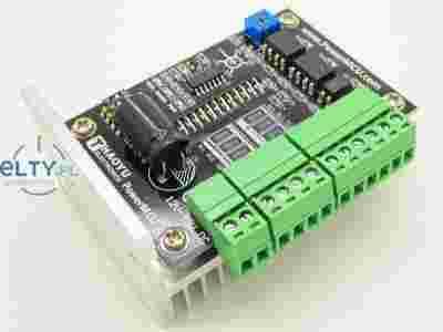
TB6600 1 axis Stepper Motor 2-phase Driver Board for CNC Router
PWM Chopper-Type bipolar Stepping Motor Driver IC
The TB6600HQ is a PWM chopper-type single-chip bipolar sinusoidal micro-step stepping motor driver.
Forward and reverse rotation control is available with 2-phase, 1-2-phase, W1-2-phase, 2W1-2-phase, and 4W1-2-phase excitation modes.
2-phase bipolar-type stepping motor can be driven by only clock signal with low vibration and high efficiency.
TB6600 Features
- Single-chip bipolar sinusoidal micro-step stepping motor driver
- BiCD 0.13 (50 V) process
- Ron (upper + lower) = 0.4 Ω (typ.)
- Forward and reverse rotation control available
- Selectable phase drive (1/1, 1/2, 1/4, 1/8, and 1/16 step)
- Output withstand voltage: VCC = 50 V
- Output current: IOUT = 5.0 A (absolute maximum ratings, peak, within 100ms) IOUT = 4.5 A (operating range, maximal value)
- Packages: HZIP25-1.00F
- Built-in input pull-down resistance: 100 kΩ (typ.)
- Output monitor pins (ALERT): Maximum of IALERT = 1 mA
- Output monitor pins (MO): Maximum of IMO = 1 mA
- Equipped with reset and enable pins
- Stand by function
- Single power supply
- Built-in thermal shutdown (TSD) circuit
- Built-in under voltage lock out (UVLO) circuit
- Built-in over-current detection (ISD) circuit
Overview
The module working voltage is 12~48V. it can used to drive a stepper motor. The stepper motor is suitable for 4.5A 2-phase model.
1. Excitation Settings
The excitation mode can be selected from the following eight modes using the M1, M2 and M3 inputs. New excitation mode starts from the initial mode when M1, M2, or M3 inputs are shifted during motor operation. In this case, output current waveform may not continue.
| INPUT |
Mode(Excitation) |
| M1 |
M2 |
M3 |
| OFF |
OFF |
OFF |
Standby mode (Operation of the internal circuit is
almost turned off.) |
| OFF |
OFF |
ON |
1/1 (2-phase excitation, full-step) |
| OFF |
ON |
OFF |
1/2A type (1-2 phase excitation A type)
( 0% - 71% - 100% ) |
| OFF |
ON |
ON |
1/2B type (1-2 phase excitation B type)
( 0% - 100% ) |
| ON |
OFF |
OFF |
1/4 (W1-2 phase excitation) |
| ON |
OFF |
ON |
1/8 (2W1-2 phase excitation) |
| ON |
ON |
OFF |
1/16 (4W1-2 phase excitation) |
| ON |
ON |
ON |
Standby mode (Operation of the internal circuit is
almost turned off.) |
Note: To change the exciting mode by changing M1, M2, and M3, make sure not to set M1 = M2 = M3 = L or M1 = M2 =M3 = H.
Standby mode
The operation mode moves to the standby mode under the condition M1 = M2 = M3 = L or M1 = M2 = M3= H.
The power consumption is minimized by turning off all the operations except protecting operation.
In standby mode, output terminal MO is HZ.
To release the standby mode, release the condition of M1 = M2 = M3 = L or M1 = M2 = M3 = H.
Input signal is not accepted for about 200 μs after releasing the standby mode.
2. LATCH Settings
| INPUT |
Mode(Excitation) |
| Latch/Auto |
| ON |
Automatic return |
| OFF |
Latch |
Note: Latch/Auto mean Select a return type for thermal shutdown (TSD) circuit and over-current detection (ISD) circuit., when TSD or ISD is happen, the WARN led will work.
M1 = M2 = M3 = LATCH = ON
M1 = M2 = M3 = LATCH = OFF
3. Output current mode
0.5A mode
2.5A mode
4.5A mode
Shipping List
- HY-TB6600-Module X 1