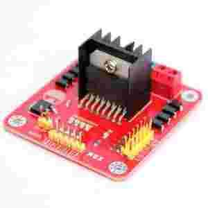
The L298N driver module, using ST' L298N chip, can directly drive two 3-30V DC motor, and provide a 5V output interface, power for 5V single-chip circuitry , support 3.3VMCU control. you can easily control the DC motor speed and direction, also control the 2-phase stepper motor. It is essential for smart car.
SPECYFIKACJA TECHNICZNA
Driver: L298N Dual H Bridge DC Motor Driver IC
Driven part of the terminal supply area Vs: +5 V ~ +35 V; such as the need to take power within the board, the supply area Vs: +7 V ~ +35 V
Driven part of the peak current Io: 2A
The logical part of the terminal supply area Vss: +5 V ~ +7 V (can take power within the board +5 V)
The logical part of the operating current range: 0 ~ 36mA
Control signal input voltage range:
Low:-0.3V ≤ Vin ≤ 1.5V
High: 2.3V ≤ Vin ≤ Vss
Enable signal input voltage range:
Low: -0.3 ≤ Vin ≤ 1.5V (control signal is invalid)
High: 2.3V ≤ Vin ≤ Vss (control signal active)
Maximum power consumption: 20W (when the temperature T = 75 ℃)
Storage temperature: -25 ℃ ~ +130 ℃
Other Extensions: control of direction indicators, the logic part of the plate to take power interface.
Driver Board Size: 55mm * 60mm * 30mm
Drive plate Weight: 33g
SPOSÓB STEROWANIA
- ENA and ENB enable the H-bridges A and B, respectively
- Jumpers U1-U4 allow for easily tying IN1-IN4 to 5V. To allow for full control of the H-Bridges remove these jumpers. IN1 and IN2 control bridge A; IN3 and IN4, bridge B. The following example specifies control of bridge A using IN1 and IN2, but the same logic applies using IN3 and IN4 to control bridge B
- To move the motor forward: IN1=H, IN2=L, ENA=H
- To move the motor backwards: IN1=L, IN2=H, ENA=H
- To quickly stop the motor: IN1=L, IN2=L, ENA=H OR IN1=H, IN2=H, ENA=H
- To slowly stop the motor (free-run stop): ENA=L (IN1 and IN2 ignored)
- The 5V_EN jumper enables the onboard regulator
- The CSA and CSB pins are the current sense pins for bridge A and bridge B and can be used to sense the motor current. These are also broken out to jumpered headers. If not using current sense leave the pins jumpered to ground
PINOUT (opis wyprowadzeń)
SCHEMAT MODUŁU
STEROWANIE JEDNYM SILNIKIEM DC
STEROWANIE DWOMA SILNIKAMI DC
STEROWANIE SILNIKIEM KROKOWYM
RE18KAT
Do pobrania
| SCHEMAT MODUŁU |
| DOKUMENTACJA STEROWNIKA L298 |