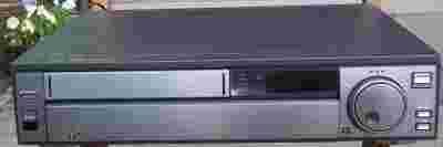
Ta strona wykorzystuje pliki cookies. Korzystając ze strony, zgadzasz się na ich użycie. OK Polityka Prywatności Zaakceptuj i zamknij X

JVC HR-S5800EG

14-06-2012, 4:41
Aukcja w czasie sprawdzania była zakończona.
Cena kup teraz: 49.99 zł     
Użytkownik lavadia2
numer aukcji: 2345453130
Miejscowość Boleszkowice
Wyświetleń: 81   
Koniec: 17-05-2012 09:41:41

Dodatkowe informacje:
Stan: Używany
info Niektóre dane mogą być zasłonięte. Żeby je odsłonić przepisz token po prawej stronie. captcha


693 [zasłonięte] 949

[zasłonięte]@o2.pl


Paczki sa wysylane kurierem UPS, kazda paczka jest ubezpieczona wiec prosze otworzyc ja w obecnosci kuriera w celu sprawdzenia czy nie ulegly paczki uszkodzeniu.


przelew bankowy

PKO BP SA

28 1020 [zasłonięte] 1[zasłonięte]9540002 [zasłonięte] 006485

Po zakupie nie ma mozliwosci zrezygnowania z przedmiotu.

Czas realizocji wplaty i zamowienia do siedmi dni roboczych, potem nastepuje postepowanie egzekucyjne wedlug zasad allegro.

Cena jest ostateczna i nie podlega negocjacji.


Gwarantujemy satysfacje i zadowolenie z naszych uslug!!

Dla panstwa bezpieczenstwa kazda paczka jest ubezpieczona, wiec prosimy o otwarcie jej w obecnosci kuriera,jezeli w trakcie transportu sprzed ulegl by jakiemus uszkodzeniu gwarantujemy zwrot kosztow , pod warunkiem ze zostanie ona otwarta przy przewozniku .


JVC  

HR-S5800EG


darmowy hosting obrazków


Podstawowe dane techniczne oraz funkcje użytkowe:


Witam na mojej aukcji posiadam do sprzedania wideo renomowanej firmy JVC, stan wizualny bardo dobry widoczny na zdjeciach. Nie sprawdzany z kaseta, kabel wuro dziala. po podlaczeniu do pradu nie wykazuje zadnych uszkodzen, ale nie jest mi wiadomo jak odbiera kasety.


  • SP PB switching point on servo circuit.
  • Checking the oscillator frequency: power supply.
  • Colour level and colour balance adjustment in SP REC mode.
  • Y-comb gain on video circuit.
  • Setting the EE level: video.
  • SP slow tracking preset on servo circuit. (HRS5800EG tip from JVC)
  • YNR balance adjustment - Video circuit.
  • Colour flickering. Distortion at upper picture edge (black and white rectangles).
  • Setting the EE levl: audio. (HRS5800EG tips)
  • VCO adjustment. (with circuit diagram extract)
  • 2H delayed chroma on video circuit.
  • No functions on manual operation. Ok on RC. (picture attached) (JVC - HRS5800EG information)
  • Service info: pin connection of the scart socket. (HRS5800EG JVC repair tip)
  • Setting the VHS frequency response (SP): video.
  • Switches on briefly and immediately off. No other functions.
  • Setting the VHS frequency response (LP): video.
  • Adjusting the character position: screen OSD.
  • When plugging into the mains the loading motor starts immediately but blocks because there is no tape present. When a tape is present the mechanism initialises instantly but runs to the final position.
  • Adjusting the HF control voltage: tuner/IF.
  • E-E level on video circuit.
  • Adjusting the channel separation: stereo decoder.
  • Audio PB level adjustment.
  • Buzz adjustment.
  • Confirmation of oscillation on switching regulator circuit. (with circuit diagram extract)
  • Only a part of picture visible in PB. If you unlace then lace up again, another part is visible.
  • Setting the slow motion presentation: servo.
  • 4H delayed chroma signal adjustment.
  • Adjusting the audio bias: audio.
  • Audio output level adjustment.
  • REC FM level adjustment.
  • No audio (in E-E).
  • Jammed tape.
  • Adjusting the dc. voltage: power supply. (service info for JVC -HRS5800EG)
  • 0.5 H delayed colour level - video circuit. (extract of circuit diagram attached)
  • VHS mode LP frequency response and balance adjustment - Video circuit.
  • SP REC colour level and balance on video circuit.
  • 4H delayed chroma on video circuit.
  • Setting the stereo output level: stereo decoder.
  • No colour with own recordings, OK with pre-recorded tapes.
  • Second audio detector coil adjustment.
  • No functions. Dark display.
  • LP slow tracking preset adjustment - Servo circuit.
  • Setting the S-VHS frequency response (SP): Video.
  • Setting Y-NR: Video.
  • Stereo separation adjustment.
  • OSD position adjustment.
  • Timer clock.
  • Setting the input emphasis level: video.
  • Adjustment to minimum interference: stereo decoder.
  • First audio detector coil adjustment.
  • Setting the Y comb filter: video.
  • VHS mode PB Y level on video circuit.
  • Shortly after plugging in appliance does not function. Display is dark. (+ extract of circuit diagram)
  • Setting the PB head switching point (SP): servo.
  • 5Vdc output voltage on switching regulator circuit. (extract of circuit diagram attached)
  • No function or display. (part of circuit diagram displayed)
  • S-VHS mode REC FM level on video circuit.
  • Setting the VCO: tuner/IF.
  • Dead. (part of circuit diagram displayed)
  • Adjusting the oscillator background: screen OSD.
  • SECAM DET - video circuit.
  • REC FM signal level in S-VHS mode. (extract of circuit diagram attached) (HRS5800EG JVC repair tip)
  • SECAM detection adjustment - Video. (+ extract of circuit diagram)
  • S-VHS mode LP frequency response and balance - video circuit.
  • 0.5H delayed colour signal adjustment.
  • No start-up.
  • Adjusting the REC FM level: audio.
  • Adjustment of Y level in PB, VHS mode.
  • Image distortions in upper and lower image part. Image may also be completely distorted (as if dirty head disk).
  • Background colour adjustment.
  • Intermittent audio.
  • S-VHS mode SP frequency response and balance - video circuit. (HRS5800EG tip from JVC)
  • Audio bias level - audio circuit.
  • Setting the audio detector 1: stereo decoder.
  • No OSD.
  • VHS mode SP frequency response and balance adjustment - Video circuit.
  • Setting the audio PB level: audio.
  • Colour level adjustment.
  • Setting the S-VHS frequency response (LP): video. (JVC - HRS5800EG information)
  • E-E level adjustment.
  • No PB on regular VHS. SVHS OK.
  • Setting the timer clock: timer.
  • LP REC colour level and balance on video circuit.
  • No display. (extract of circuit diagram attached)
  • Occasionally tape is not fully wound back into the cassette in Eject. Lacing motor hums at switch on. Switches off after a few secs.
  • No function. Cassette is accepted. "-" appears in the channel no. in the display.
  • Adjusting the audio detector 2: stereo decoder.
  • Sub emphasis input level on video circuit.
  • Loading problems.
  • Setting the Y comb filter level: video.
  • Adjustment of Y level in PB, S-VHS mode. (HRS5800EG tip from JVC)
  • Unstable picture.
  • Will not accept tapes. Lacing motor keeps running in lacing out position.
  • Colour level and colour balance adjustment in LP REC mode.
  • Adjusting the colour level: tuner/IF.
  • S-VHS mode PB Y level on video circuit.
  • 2H delayed chroma signal adjustment 
  •  


  • PRZESYLKA

    przesylka kurierska UPS ubezpieczona 22zl


  •  


     llllll.jpg

    lllll.jpg


    llll.jpg


    lll.jpg


    ll.jpg


    l.jpg