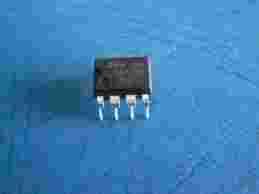
UA741 10 szt
Układ scalony wzmacniacz operacyjny 14P 3-18V 1MHz SO8
One of the cheapest and most-popular OP-AMP is the 741.
The pinout for an LM741 is shown below:
The basic parameters for a 741 are:
Rail voltages : +/- 15v DC (+/- 5v min, +/- 18v max)
Input impedance: approx 2M
Low Frequency voltage gain: approx 200,000
Input bias current: 80nA
Slew rate: 0.5v per microsecond
Maximum output current: 20mA
Recommended output load: not less than 2k
The following diagram shows the 741 in a typical audio circuit:
From the discussion above we can see how the circuit above sets its operating conditions.
1. The "+" input sits at half-rail voltage via the two 47k voltage-divider resistors.
2. This makes the output go HIGH and the voltage on the "–" input increases until it is just below the "+" input. (The "–" input cannot rise above the "+" input as this will make the output of the OP-AMP go LOW).
3. The end result is the OP-AMP is "half-turned-on" and any increase or decrease in voltage on the "–" input will make the output go LOW or HIGH.
Don't forget: the output will move in the opposite direction to the voltage applied to the "–" input.
|
HOW DOES THE OP-AMP AMPLIFY?
|
The circuit above is set to have a gain of 100 via the 100k/1k resistors. These two resistors form a voltage divider. We have seen the ratio of the two resistors produces the gain of the stage.
Suppose the voltage on the input rises 1mV.
This rise will pass through the 100n capacitor and appear on the "–" input as a 1mV increase.
The OP-AMP will amplify this signal 100,000 times and the output will try to FALL as much as 100v - but the voltage-divider resistors come into operation as follows:
The output will fall and this will be passed to the "–" input via the 100k resistor. As soon as the output falls 100mV, the voltage seen by the "–" input will be 1/100th of 100mV or 1mV. Thus the 1mV produced by the signal will be negated by the effect of the output dropping.
The effect is slightly less than 1mV being fed back to the "–" input and the output drops 100mV.
The "–" input sees about 100th of 1mV and the output drops 100mV.
The following animation shows (in slow-motion) how the voltages flow though the OP-AMP:

